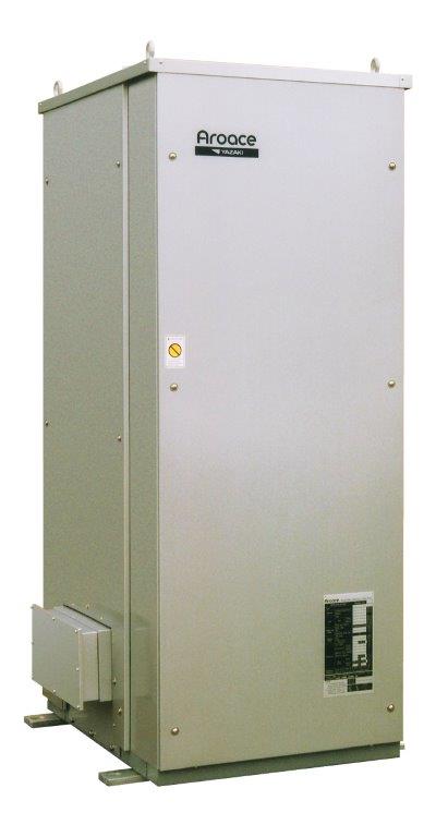

Water Fired Single-Effect Chillers and Chiller-Heaters
Specifications
Yazaki’s water-fired thermal chillers are engineered for maximum efficiency and flexibility in various industrial applications. Designed with advanced fuel switching capabilities, these chillers allow for seamless transitions between energy sources like biomass and natural gas, supporting carbon neutral and sustainable operations. Whether it's for process cooling, load shifting, or waste heat recovery, these chillers deliver reliable, cost-effective cooling solutions for demanding industrial environments.
| Model | WFC- |
SC5 |
SC/SH10 |
SC/SH20 |
SC/SH30 |
SC50 |
M100 |
||
|---|---|---|---|---|---|---|---|---|---|
| Cooling | Mbtuh |
60.0 | 120.0 | 240.0 | 360.0 | 600.0 | 1200.0 | ||
| Heating (WFC-SH Only) | Mbtuh |
--- | 166.3 | 332.6 | 498.9 | --- | --- | ||
| Chilled/Hot Water |
Cooling | °F |
54.5 Inlet / 44.6 Outlet (54.0 Inlet / 44.0 Outlet for M100) | ||||||
| Heatng | °F |
--- | 117.3 Inlet / 131.0 Outlet (WFC‐SH Models Only) | --- | |||||
| Rated Water Flow | GPM |
12.1 | 24.2 | 48.4 | 72.6 | 121.1 | 242.5 | ||
| Evaporator Pressure Loss | PSI |
7.6 | 8.1 | 9.6 | 10.1 | 6.4 | 10.5 | ||
| Max Operating Pressure5 | PSI |
85.3 (High Pressure Option Available)4 | 150.0 | ||||||
| Allowable Water Flow | % of Rated |
80% - 120% | |||||||
| Water Retention Volume | Gal |
2.1 | 4.5 | 12.4 | 19.3 | 33.6 | 32.0 | ||
| Cooling Water | Total Heat Rejection | Mbtuh |
145.7 | 291.4 | 582.8 | 874.2 | 1457.0 | 2917.0 | |
| Temperature | °F |
87.8 Inlet / 95.0 Outlet (85.0 Inlet / 95.7 Outlet for M100) | |||||||
| Rated Water Flow1 | GPM |
40.4 | 80.8 | 161.7 | 242.5 | 404.5 | 539.5 | ||
| Allowable Water Flow | % of Rated |
100%-120% | |||||||
| Absorber Pressure Loss | PSI |
5.6 | 12.3 | 6.6 | 6.7 | 6.6 | 9.6 | ||
| Condenser Pressure Loss | PSI |
5.6 | Included in Absorber | 6.6 | 6.7 | 3.2 | Included in Absorber | ||
| Max Operating Pressure5 | PSI |
85.3 (High Pressure Option Available)4 | 150.0 | ||||||
| Water Retention Volume | Gal |
9.8 | 17.4 | 33.0 | 51.3 | 87.2 | 111.5 | ||
| Heat Medium7 |
Heat Input | Mbtuh |
85.7 | 171.4 | 342.8 | 514.2 | 857.0 | 1717.0 | |
| Temperature | °F |
190.4 Inlet / 181.4 Outlet (194.0 Inlet / 176.0 Outlet for M100) | |||||||
| Allowable Temperature | PSI |
158.0 - 203.0 | |||||||
| Generator Pressure Loss | PSI |
11.2 | 13.1 | 6.7 | 8.8 | 13.6 | |||
| Max Operating Pressure | PSI |
85.3 / {No High Pressure Option} | |||||||
| Rated Water Flow | GPM |
19.0 | 38.0 | 76.1 | 114.1 | 190.4 | 195.9 | ||
| Allowable Water Flow | % of Rated |
30%-120% | |||||||
| Water Retention Volume | Gal |
2.6 | 5.5 | 14.3 | 22.2 | 39.7 | 66.0 | ||
| Electrical8 | Power Supply | 115 / 60/ 1 | 208 volts AC / 60 Hz / 3-Phase | ||||||
| Consumption2 | Watts |
48 | 210 | 260 | 310 | 670 | 620 | ||
| Minimum Circuit Amps | Amps |
0.89 | 0.6 | 0.9 | 2.6 | 4.7 | 2.4 | ||
| MOCP - Max. Fuse Size | Amps |
15 | |||||||
| Capacity Control | On - Off | Proportional or On/Off | |||||||
| Construction | Dimensions3 | Width |
Inches |
23.4 | 29.9 | 41.9 | 54.3 | 70.3 | 59.4 |
Depth |
Inches |
29.3 | 38.2 | 51.2 | 60.8 | 77.2 | 144.0 | ||
Height |
Inches |
69.1 | 74.8 | 79.1 | 80.5 | 82.1 | 88.6 | ||
| Weight | Dry |
Ibs |
805 | 1100 | 2050 | 3200 | 4740 | 10891 | |
Operating |
Ibs |
926 | 1329 | 2548 | 3975 | 5955 | 12655 | ||
| Cabinet | NEMA 3R, Silver Metallic Pre-Painted Hot Dip Zinc-Coated Sheet Steel | ||||||||
| Noise Level9 | dB(A) |
38 | 49 | 46 | 51 | 56 | |||
| Piping | Chilled/Hot Water | Inches |
1-1/4 NPT | 1-1/2 NPT | 2 NPT | 3 NPT | 4 Flanged | ||
| Cooling Water | Inches |
1-1/2 NPT | 2 NPT | 2-1/2 NPT | 3 NPT | 5 Flanged | |||
| Heat Medium | Inches |
1-1/2 NPT | 2 NPT | 2-1/2 NPT | 3 NPT | 4 Flanged | |||
- Minimum cooling water flow is 100%.
- Power Consumption does not include external pumps or fan motors.
- Height does not include removable lifting lugs, but does include level bolts. Width/Depth does not include junction box or mounting plates.
- High pressure option uses tubing that has passed UL hydrostatic testing at 300 psig.
- Do not exceed 150 PSI (1034 kPa) in any fluid circuit.
- Specifications are based upon water in all fluid circuits and fouling factor of 0.0005 ft2hr°F/Btu.
- Density of Heat Medium is 60.47 lbs/ft3, Specific Heat 1.003 BTU/lbs°F (185°F).
- Electric field wiring must be made in accordance with local regulation and must be sized to provide less than 2% voltage drop.
- Noise level is measured in a free field at a point 1m away from the cabinet and 1.5m above ground level.