
Water Fired Single-Effect Chillers and Chiller-Heaters
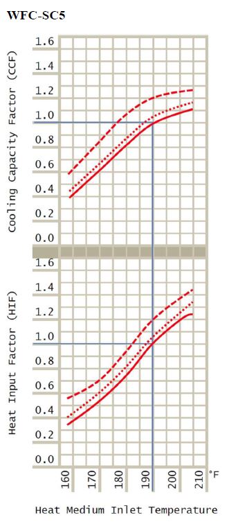
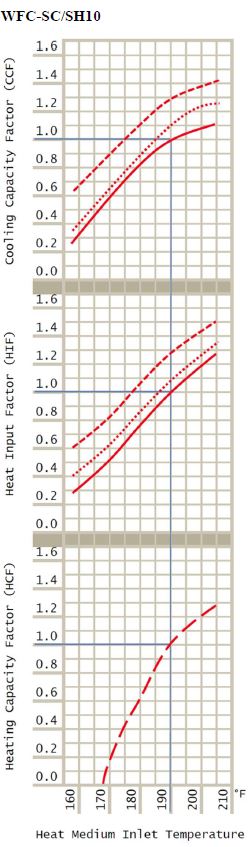
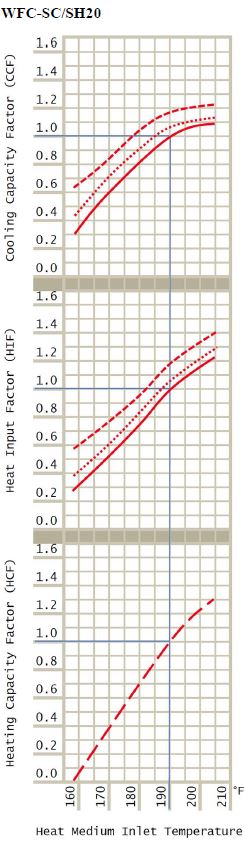
Performance Characteristics at 44.6°F (7°C)
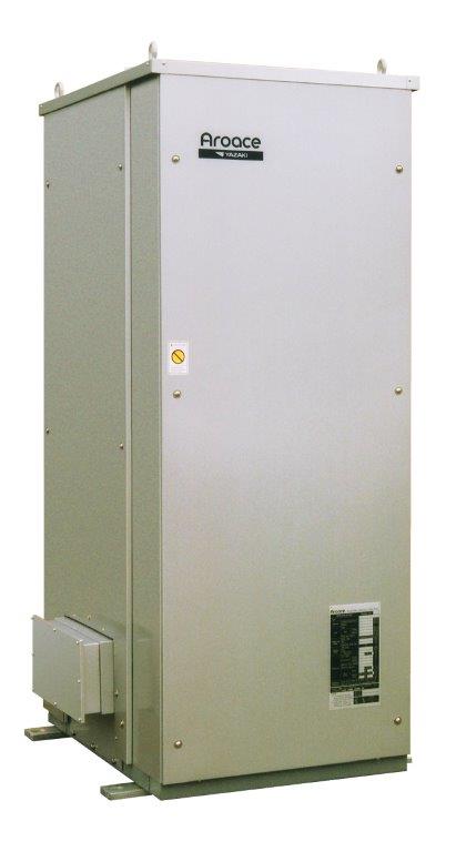
Yazaki's water-fired chiller delivers high-performance cooling solutions, featuring cutting-edge technologies such as fuel switching, biomass integration, and waste heat recovery. Designed for carbon neutral operations, these chillers offer flexible solutions for industries that require energy-efficient process cooling. With cogeneration capabilities, our chillers maximize energy use by generating both cooling and electricity.
Performance Characteristics at 44.6°F (7°C)
Notes:
-
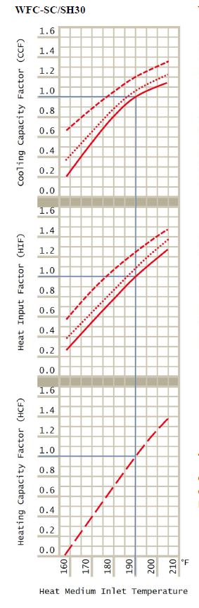
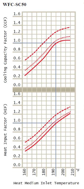
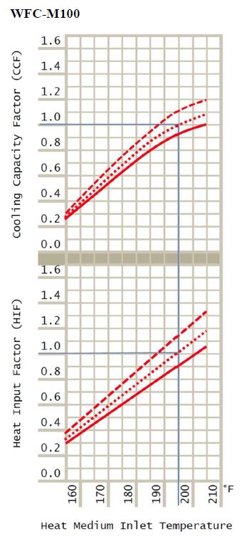
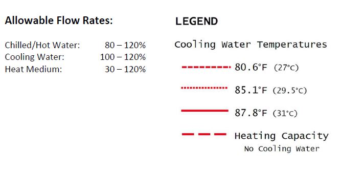
Bold blue lines indicate rated design conditions. Where these lines cross designate the Standard Rating Point.
-
All curves are based on water in all circuits flowing at rated design condition flow rates.
-
Heating Efficiency = 97%
-
Performance may be interpolated but must not be extrapolated.
-
Expanded performance curves are provided for reference only. Contact Yazaki Energy Systems, Inc. to obtain certified performance ratings from the f ac t ory or t o det ermine performance at other conditions outside the scope of this publication.
-
Performance data based upon standard fouling factor of 0.0005 ft2hr°F/BTU in all circuits.
Absorption Chiller Heat Balance
| Heat in = Heat out | |||||||
| Qg + Qe = Qc | |||||||
| Where: | Qg = Actual Heat Input to Generator | ||||||
| Qe = Actual Cooling capacity | |||||||
| Qc = Actual Heat Rejected to Tower | |||||||
| Cooling Capacity | |||||||
| Qe = CCF x HMFCF x RCC | |||||||
| Where: | Qe = Actual Cooling Capacity | ||||||
| CCF = Cooling Capacity Factor | |||||||
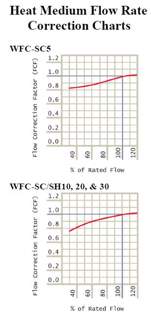
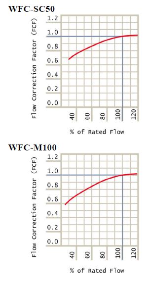
| HMFCF = Flow Correction Factor | |||||||
| RCC = Rated Cooling Capacity | |||||||
| Heat Input (Cooling) | |||||||
| Qg = HIF x HMFCF x RHI | |||||||
| Where: | Qg = Actual Heat Input to Generator | ||||||
| HIF = Heat Input Factor | |||||||
| HMFCF = Flow Correction Factor | |||||||
| RHI = Rated Heat Input | |||||||
| Heating capacity | |||||||
| Qh = HCF x HMFCF x RHC | |||||||
| Where: | Qh = Actual Heating Capacity | ||||||
| HCF = Heating Capacity Factor | |||||||
| HMFCF = Flow Correction Factor | |||||||
| RHC = Rated Heating Capacity | |||||||
| Heat Input (Heating) | |||||||
| Qg = Qh / 0.97 | |||||||
| Where: | Qg = Actual Heat Input to Generator | ||||||
| Qh = Actual Heating Capacity | |||||||
| Temperature Difference (oF) | |||||||
| Where: | |||||||
| Qx = Actual BTUH Transferred | |||||||
| Qa = Actual Flow Rate in GPM | |||||||
| Press. Drop for Nonstandard Flow (PSI) | |||||||
| Where: | |||||||
| Qa = Actual Flow Rate in GPM | |||||||
| Qr = Rated Design Flow Rate GPM | |||||||
| |||||||
| Example 1: | ||||
|---|---|---|---|---|
| Heat medium input temperature..........195°F | ||||
| Heat medium flow............................114.1 GPM | ||||
| Cooling water inlet temperature..........85.1°F | ||||
| Cooling water flow...........................242.5 GPM | ||||
| Chilled water outlet temperature.........44.6°F | ||||
| Hot water outlet temperature.............131°F | ||||
| Chilled/hot water flow........................72.6 GPM | ||||
| Chiller-heater model.......WFC-SH30 | ||||
|
Refer to Performance Charts for Curves (Page 7) and to Specifications (Page 5) for Rated Design Information on the Model WFC-SC/SH30. |
||||
| 1. | Available Cooling Capacity: | |||
| CCF at 195°F Heat Medium = 1.12 | ||||
| Heat Medium Flow = 114.1 / 114.1 = 100% | ||||
| HMFCF for 100% Flow Rate = 1.0 | ||||
| Rated Cooling Capacity = 360.0 Mbtuh | ||||
| Qe = 1.12 x 1.0 x 360.0 = 403.2 Mbtuh (33.6 T) | ||||
| ||||
| Chilled Water
| ||||
| 2. | HEAT INPUT (COOLING): | |||
| HIF for 195°F Heat Medium = 1.177 | ||||
| HMFCF for 100% Flow Rate = 1.0 | ||||
| Rated Heat Input = 514.2 Mbtuh | ||||
| Qg = 1.17 x 1.0 x 514.2 = 601.6 Mbtuh Heat Input | ||||
| ||||
|
Heat Medium
| ||||
| 3. | HEAT REJECTED TO COOLING TOWER: | |||
| Qc = Qg + Qe | ||||
| Qc = 601.6 + 403.2 = 1004.8 Mbtuh | Required minimum flow rate = 242.5 GPM | The cooling tower selected must be capable of rejecting a minimum of 1004.8 Mbtuh at a minimum flow rate of 242.5 GPM. | ||
|
||||
| Cooling Water
|
||||
|
4. |
AVAILABLE HEATING CAPACITY: | |||
| HCF at 195°F Heat Medium = 1.12 | ||||
| HMFCF for 100% Flow Rate = 1.0 | ||||
| Rated Heating Capacity = 498.9 Mbtuh | ||||
| Qh = 1.12 x 1.0 x 498.9 = 558.8 Mbtuh | ||||
|
||||
| Hot Water
|
||||
|
5. |
HEAT INPUT (HEATING): | |||
| Qg = Qh / 0.97 = 558.8 / 0.97 = 576.1 Mbtuh Heat Input | ||||
|
||||
| Heat Medium
|
||||
| Example 2: | ||||
|---|---|---|---|---|
| Heat medium input temperature..........203°F | ||||
| Heat medium flow............................57.0 GPM | ||||
| Cooling water inlet temperature..........85.1°F | ||||
| Cooling water flow...........................242.5 GPM | ||||
| Chilled water outlet temperature.........44.6°F | ||||
| Hot water outlet temperature.............131°F | ||||
| Chilled/hot water flow.......................72.6 GPM | ||||
| Chiller-heater model........WFC-SH30 | ||||
|
Refer to Performance Charts for Curves (Page 7) and to Specifications (Page 5) for Rated Design Information on the Model WFC-SC/SH30. |
||||
| 1. | Available Cooling Capacity: | |||
| CCF at 203°F Heat Medium = 1.22 | ||||
| Heat Medium Flow = 57.0 / 114.1 | ||||
| Heat Medium Flow = 50% | ||||
| HMFCF for 50% Flow Rate = 0.86 | ||||
| Qe = 1.22 x 0.86 x 360.0 = 377.7 Mbtuh (31.5 T) | ||||
| ||||
| Chilled Water
| ||||
| 2. | HEAT INPUT (COOLING): | |||
| HIF at 203°F Heat Medium = 1.35 | ||||
| HMFCF for 50% Flow Rate = 0.86 | ||||
| Rated Heat Input = 514.2 Mbtuh | ||||
|
Qg = 1.35 x 0.86 x 514.2 = 597.0 Mbtuh Heat Input | ||||
| ||||
| ||||
| 3. | HEAT REJECTED TO COOLING TOWER: | |||
| Qc = Qg + Qe | ||||
| Qc = 597.0 + 377.7 = 974.7 Mbtuh | ||||
| Required minimum flow rate = 242.5 GPM | ||||
| The cooling tower selected must be capable of rejecting a minimum of 974.7 Mbtuh at a minimum flow rate of 242.5 GPM. | ||||
|
||||
| Cooling Water
|
||||
|
4. |
AVAILABLE HEATING CAPACITY: | |||
| HCF at 203°F Heat Medium = 1.33 | ||||
| HMFCF for 50% Flow Rate = 0.86 | ||||
| Rated Heating Capacity = 498.9 Mbtuh | ||||
| Qh = 1.33 x 0.86 x 498.9 Mbtuh = 570.6 Mbtuh | ||||
|
||||
| Hot Water
|
||||
|
5. |
HEAT INPUT (HEATING): | |||
| Qg = Qh / 0.97 = 570.6 / 0.97 = 588.2 Mbtuh Heat Input | ||||
|
||||
|
||||